

CNC ENGRAVINGS ON IRREGULAR SURFACES WITH FLATNESS CORRECTION
When engraving, marking or milling with a CNC machine the difference in the planarity of the surface you are machining can present problems, especially when you have to work with a cutting depth of only a few millimeters or even less.
To maintain a consistent depth of cut in a surface that’s not completely flat is a nightmare. You could have areas with visible engravings and other areas without any because the cutting tool did not make contact with all of the material.
Situations like these are frequent in all sectors, and with any material, but it is certainly a recurring issue in the processing of stone because a slab of marble or granite, even if it has been milled level, is anything but perfectly regular. A marble slab between one point and another may have differences in thickness of a few millimeters, which can be significant when making engravings in the italic font as there are points where the cutting depth is really minimal and can be missed.
Automatic Flatness Correction

An elegant solution to this problem is Automatic Flatness Correction, which involves these two simple steps:
-
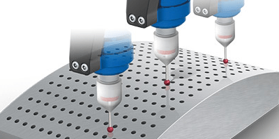
Flatness Acquisition: a scan of the surface to be machined by means of a Touch Probe for CNC machines.
-
Z-Correction Enabling: to automatically correct, via software, the height values in Z to ensure a regular engraving depth across an irregular surface.
The Automatic Correction of Flatness is a feature that must be implemented at the software level by Numerical Control. Obviously, this feature is not available on all CNC machines but because it’s really useful for stoneworking we have developed a solution for it. This is included as an option in our CNC Routers for marble working – for a small additional price.
The Flatness Acquisition is nothing more than a scan of the workpiece using the touch probe to map the material’s surface.

This flatness measurement can be implemented in various ways. The strategy we have chosen is to use the Flatness Acquisition in Selected Areas. This allows you to define areas you scan, even those that are far away from each other, which avoids mapping the entire slab. This saves you time when the writing or engraving is made only on a small portion of the material’s surface.
Let’s see in detail how this works.
Flatness Acquisition and surface mapping phase
A flatness correction algorithm is made of two main phases. The first one is the Flatness Acquisition to map the surface by a touch probe installed in the spindle.
The numerical control executes a path on the workpiece surface and through the probe acquires the points and then stores the value of the Z-axis coordinate at the exact point where the probe touches the material.
Below you can see an example of the route taken to acquire the points in a given area. In this way, the control has created a map of points that will be used during the engraving phase to compensate for the irregularities of the slab’s thickness.

Compensation phase and calculation of the Z value
During the processing, the control uses the acquired points map to calculate the value of Z that is necessary to compensate for the difference in the planarity of the surface. The calculation is based on a weighted average formula in which the four closest points that have been acquired are considered and calculated.
We have drawn this example in the following image, which represents a processing point within a hypothetical square that has points 1 – 2 – 11 and 12 as vertices.
During the machining, the numerical control automatically executes the calculation, which results in the compensation value of the Z-axis coordinate point by point.
The Weighted Average in our case requires that the calculated value depend on the distance of the processing point from the four acquired points representing the vertices of the square around the machining point. In particular, Point 2 will be the one that will have the biggest weight in the calculation because it is the closest, followed by Point 1, then Point 11 and finally Point 12.

Implementation of the Flatness Correction by Areas

In our CNC machines, we have installed an advanced version of Flatness Correction using an algorithm by areas.
The Flatness Correction by Areas feature allows you to define up to ten separate scanning areas within a single workpiece. This avoids having to scan the entire piece. The feature is indispensable when processing very large slabs.
The panel of the Flatness Correction feature in our CNC machines:
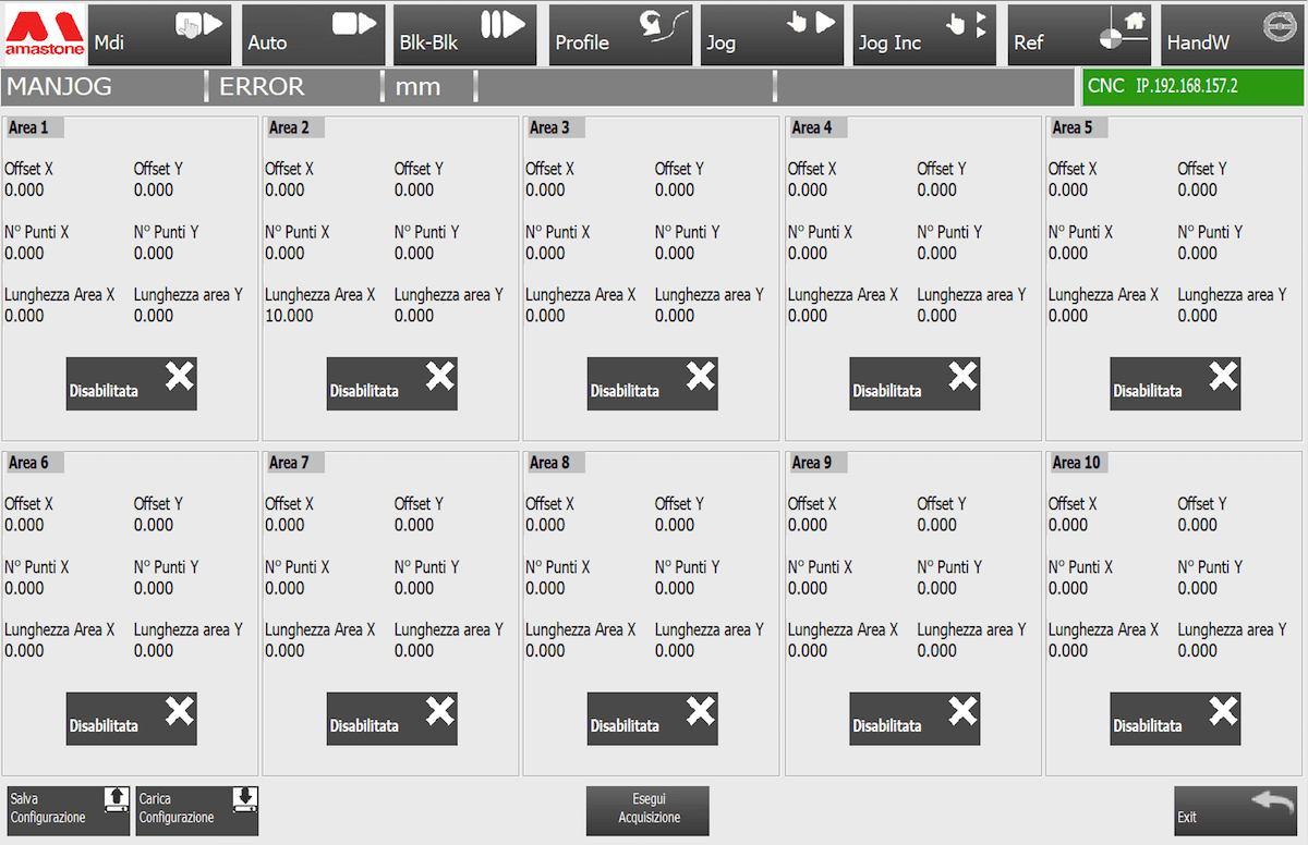
Flatness Correction Panel In Amastone Cnc Machine For Marble
For each area these are the scan parameters that can be defined:
• X Offset: coordinate of the X-axis at the beginning of the scanning area
• Y Offset: coordinate of the Y-axis at the beginning of the scanning area
• X area length: length in millimeters of the area to be scanned along the X axis
• Y area length: length in millimeters of the area to be scanned along the Y axis
- Number of points X: number of points to be acquired along the X axis
- Number of points Y: number of points to be acquired along the Y axis
Once these parameters have been set, the control will automatically calculate the distance between one point and the next. The different areas can then be activated and deactivated independently.
After scanning the first active area, the control automatically switches to the next one, moving to the X-Offset / Y-Offset point. Given the large number of parameters, you are able to save the configuration of these areas to be imported at a later date.

Conclusion
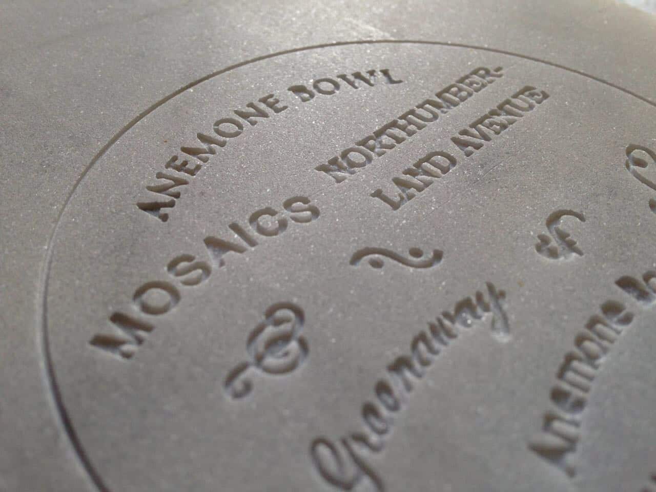
Engravings In Marble
In CNC machining, having a function to compensate for irregularities in a material’s surface is essential. Whether it be a slab of wood, marble or any other material their surfaces are never perfectly flat and these irregularities can undermine your final work when you need to make engravings and writings that are not cut deep into the surface.
To solve this problem some CNC machines provide the functionality of Flatness Correction that allows the automatic modification of the coordinates of the Z height during processing. In this way, it is possible to compensate for the irregularities of the material and therefore to obtain incisions at regular depth throughout the workpiece.
The implementation of Flatness Correction involves the measurement of regular points across a given surface to be taken. This is done using a suitable touch probe.
The strategies of acquisition and compensation can be different. We have chosen Flatness Correction by areas because that allows the user to select up to ten specific work areas rather than scan the whole workpiece. This saves you time and increases your production efficiency. These can even be saved and used again at a later date.
We have chosen the weighted average formula to calculate the value in Z of the working point to increase the precision and mitigate the differences between one point and another.
In our experience, this strategy not only saves you time but also increases the quality of your products. If you’d like to discuss this further with a member of the Amastone team please do leave a comment in the message box below or give us a call.


 Diamond Blades
 Blade for power cutters, masonry saws and floor saws
 Polishing Machine Tools for Stone, Marble and Granite
 Edge polishing abrasives
 Edge polishing diamonds
 Texture tooling
 Adhesives and glue
 Ceramic, Granite and Marble Drill Bits
 Diamond Cloths
 Stone fabrication accessories
 Stone Carving Tools for Sculpting Marble and Granite
 Diamond Wires for Granite and Marble Quarries
 Portable Router Tools Handheld Bits
 Cemetery and Mausoleum Accessories
 Measuring Tools
 Sink and Worktop Mounting Components
 Tileable Stainless Steel Sinks
 Waste Kits
 Basin Brackets
 Fixing Systems
 Tile cutters
 Electric Tile Cutters
 Large Slab Handling
 Rail Tile Cutters
 Vibrating Suction Cups
 Alignement Suction Cups
 Tiling Accessories
 Grouting Tools
 Mixers
 Tileable Components
 Worktables
 Tile Levelling
 Montolit Spare Parts
 CNC Glass Tools
 CNC Wood Tools
 CNC Vacuum Cups
 CNC Tool Holders
 CNC Tool Forks
 CNC Adapters and Tool Extensions
 CNC Sensors and Measuring Tools
 Positioning Alignment Lasers
 Polishing Pads for Angle Grinder
 Sanding discs for angle grinders
 Angle Grinder Cutting Blades
 Diamond Core Drill Bits
 Grinding Cup Wheels
 Diamond Profile Wheels
 Backing Pads
 Grinder Dust Guards
 Angle Grinder Accessories
 Material Handling
 Lifting Clamps
 Manual Lifting Suction Cups
 Handling Equipment Parts
 Manzelli Spare Parts
 Grabo Spare Parts
 Power Tools
 Grinders
 Rotary Multi Tools
 Power Drills
 Multi Tools Accessories
 Power Tool Cases
 Masonry Equipment and Machines
 Machinery
 Vacuum cleaners
 Electrical Spare Parts
 Water Cooling Pipes
 Personal Protective Equipment
 Packaging
 Floor Pads
 Floor Brushes
 Polishing Powder
 Floor Diamond Resin Tools
 Floor Machines
 Floor Machine Accessories Spare Parts
Hello,
is it possible to use that feature on very small objects like jewelry
thank you
Hello, for jewelry i think it’s not suitable
To reduce the time involved in the engraving process for a lettered plaque, why not trace only the path of the cutter, not scan the general area?.